This guide provides step-by-step instructions for installing the MoboKey Pro device in cars with a Key Start System. A good understanding of the car’s electrical system is required. For the best results, installation by a trained car electrician is recommended.
Car Types
- Key Start: Cars requiring a key in the ignition to start.
- Push Start: Cars with a smart key and push-button ignition (not covered here).
This guide focuses on the Key Start System.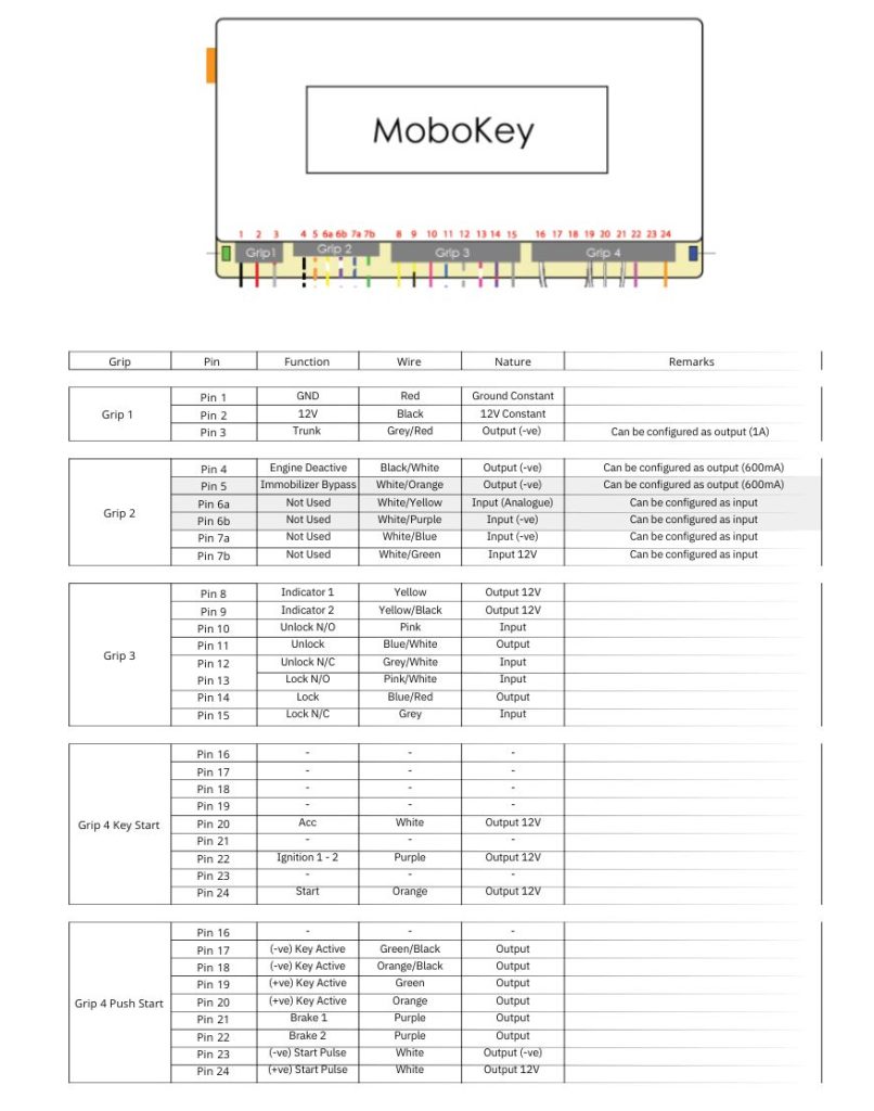
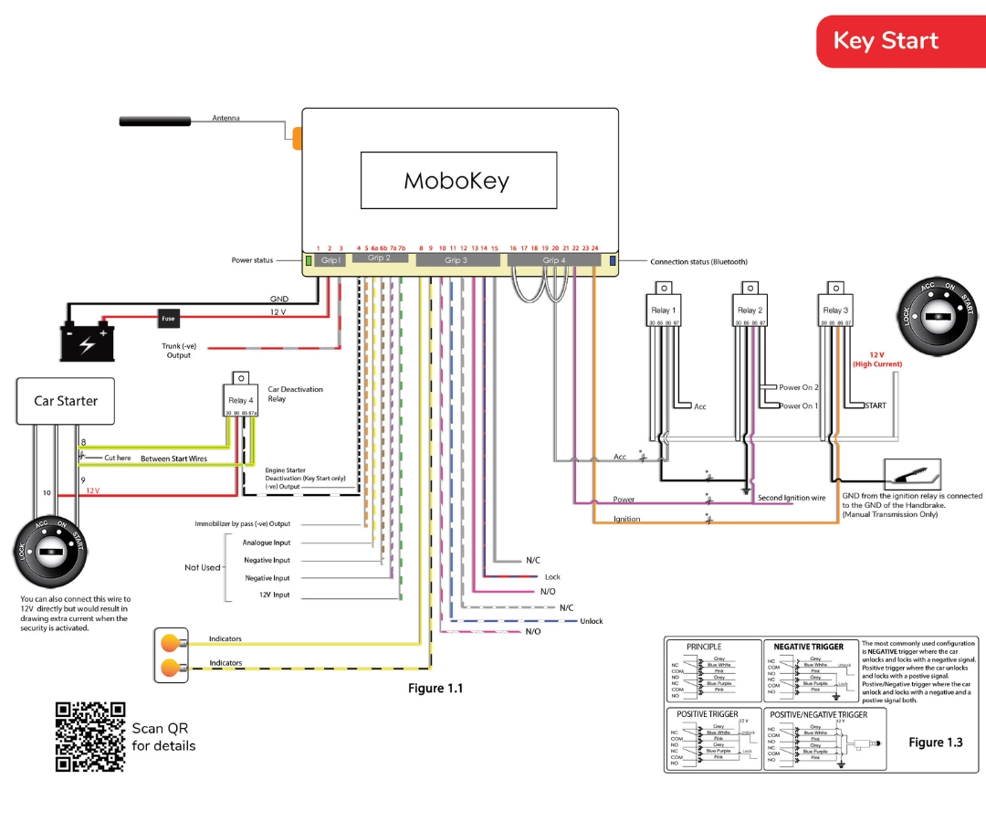
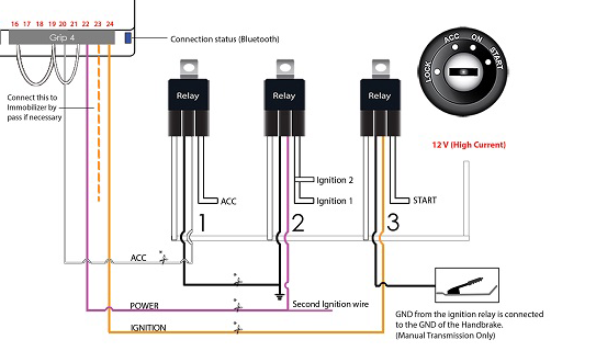
Attach the 3rd relay as shown in Figure 1.1 with the GND of the hand-brake to prevent the car from starting when not in the handbrake. This is necessary for cars with manual transmissions to prevent them from starting when in gear other than neutral.
Car Types
- Key Start: Cars requiring a key in the ignition to start.
- Push Start: Cars with a smart key and push-button ignition (not covered here).
This guide focuses on the Key Start System.
Step 1: Device Power Connection
-
- Connect Pin 1 (Black) of Grip 1 to the car’s Ground (GND).
- Connect Pin 2 (Red) to the 12V constant supply from the car battery.
Step 2: Trunk Control (Optional)
- For cars with an electronic trunk release:
- Connect Pin 3 (Grey/Red) to the negative trigger wire of the trunk release system.
Step 3: Starter Deactivation/Immobilizer Bypass/Inputs
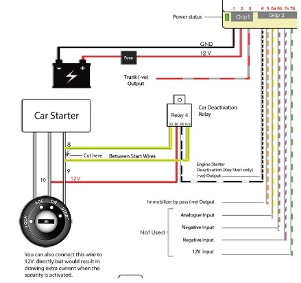
- Attach the Black/White wire (Pin 4 of Grip 2) to an engine starter deactivation relay, installed between the starter wires. This ensures enhanced security by disabling the starter when the system is armed.
-
White/Orange wire, pin 5 gives a GND signal that can be used for the immobilizer bypass unit. This wire gives the signal until the ignition is active.
- The next 4 pins in Grip 2, 6a, 6b, 7a, and 7b are extra pins for special requirements.
Step 4: Lock and Unlock Door Configuration

Negative Trigger (Standard Protocol):
- Locate the lock/unlock wires in the door power window module using a multimeter.
- Connect Grip 3 as follows:
Pin 11 (Blue/White) to the unlock wire.
Pin 14 (Blue/Red) to the lock wire.
Pins 10 & 13 (Pink) to Ground.
Test the lock/unlock function via the MoboKey app.
Note: For ease of installation, trace wires back to the car column below the dashboard instead of opening the door trim.

Negative – Positive Trigger:
- Locate the lock/unlock wires in the door power window module using a multimeter.
- Connect Grip 3 as follows:
- Pin 11 (Blue/White) to the unlock wire.
- Pin 14 (Blue/Red) to the lock wire.
- Pins 10 & 13 (Pink) to Ground.
- Pins 12 & 15(Grey) to Positive.
- Test the lock/unlock function via the MoboKey app.
Refer to the Figure 1.3 in the instruction manual for more clarity.
Step 5: Indicators
- Identify indicator wires using a multimeter by testing the voltage when activating turn signals.
- Connect Grip 3 as follows:
- Pin 8 (Yellow) to the right indicator.
- Pin 9 (Yellow/Black) to the left indicator.
Step 6: Remote Start Setup
- First, open up cover around the ignition switch. Take out wires of ACC, Power/On, and Starter. Some cars have built-in relays while others need to attach external relays. Expose the car’s ignition switch wiring.
- Connect Grip 4 as follows:
- Pin 20 (White) to the ACC wire.
- Pin 22 (Purple) to the Ignition wire.
- Pin 24 (Orange) to the Starter wire.
- If the car is older you can use the relays provided by connecting the common 12V wire and ACC, Ignition and Start respectively.
- In some cases there are two ignition inputs to start the media console. You can connect the spare the ignition wire with to media console wire.
*Cut the wires as at the marked points and connect directly if the car is already equipped with internal relays.
*Cars having thin wires less than 2.5mm in diameter coming out of the key ignition switch have internal relays.
For Manual Transmission Cars:
- Ensure the negative wire of the relay is connected to the handbrake’s Ground (GND). This prevents the engine from starting unless the handbrake is engaged.
Step 7: Security Configuration
- Cut the car’s starter wire at and connect both ends to the green wires of the engine starter deactivation relay.
Step 8: Immobilizer Bypass (If Applicable)

- Remove the immobilizer chip from the key fob.
- Place the chip near the ignition keyhole receiver to deactivate the immobilizer.
- Verify that the immobilizer light turns off when starting the car via the MoboKey system.
Step 9: Delete the Device(Installer Instruction)
If you are the installer, you can delete the device after testing the connections by Selecting My Cars and Delete the Car.
Device Output Types
The MoboKey device provides the following types of outputs:
- Lock and Unlock Signals:
- Negative/Positive triggers for lock/unlock functions.
- Configured via Pins 10, 11, 14 and 15 on Grip 3.
- Indicator Signals:
- Provides 12V Positive signals to the left and right indicator lights.
- Configured via Pins 8 and 9 on Grip 3.
- Starter Signals:
- Provides a 12V Positive High-Current Output for remote start.
- Configured via Pin 24 (Orange) on Grip 4.
- ACC and Ignition Signals:
- Pin 20 (White) delivers a 12V output for the ACC circuit.
- Pin 22 (Purple) delivers a 12V output for the Ignition circuit.
- Trunk Output:
- Negative trigger output for the trunk release function.
- Configured via Pin 3 (Grey/Red) on Grip 1.
- Engine Starter Deactivation:
- Negative trigger via Pin 4 (Black/White) on Grip 2 to disable the starter.
Watch Installation Video

