Car Access Module (CAM) Basic and plus have the same hardware and the wiring is the same. You can read more about the features here.
About the hardware:
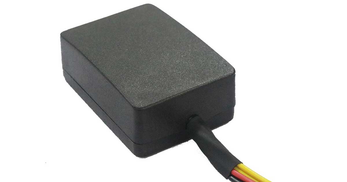
Car Access Module (CAM) is a device specifically designed for car-sharing businesses. It’s a universal device that can be installed in any car.
Device Features:
- Lock / Unlock
- Engine Deactivation
- Indicator Flashing
Devices Specifications:
- 13 Connectors
- Operating Voltage: 12V
- Standby Current: 5mA
- Size: 50 mm x 70mm x 25mm
How to wire the hardware:
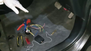
For installing the device, we will require Cutter, Splicer, Automotive Circuit tester, Screwdriver, T-rod, and tape.
Connecting 12V and GND
- Open the side panel. We need to find the wire which gives out a constant 12 V.
- Connect the clamp of the circuit tester on the body of the car and start checking the wires for the bulb to light up.
- Check for the wire using the tester. A constant 12V wire will light it up.
- Unscrew the bolt using the T rod to connect the black wire (Negative) of the device with the car body earth.
- Splice the wire to get an extra length of copper to connect it around the screw.
- Screw the bolt using the T rod after connecting it.
- Connect the red wire(12V) from the device after splicing 12V wire from the car.
- After connection, insulate the wires using electrical tape.
Connecting Lock and Unlock
- Now we will identify the lock and unlock wires using the same circuit tester!
- Using the circuit tester, we will connect with the wires in the connectors. Check which wire triggers lock and unlock.
- These are the lock and unlock wires.
- After tracing the wires for lock and unlock, connect the blue wire on the lock and green wire with unlocking wire.
- After connection, insulate the wires using electrical tape.
Connecting Indicators
- After connecting lock/unlocks wires, we will trace and then connect the left and right indicators light one by one.
- First of all, turn on the hazard lights. Once the hazard lights are on, we trace the wires which give out 12V to turn on the hazard lights.
- Now, trace the indicator from the connector in a similar fashion!
- Once the indicator wire is traced from the connector, splice the wire and connect the yellow wire from the traced wire.
- After connection, insulate the wires using electrical tape.
- For the second indicator wire, we will have to extend the wire. As in this case, it on the other side of the car.
- Extend the wire, and take it to the other side from behind the panel, so that it is not visible.
- Remove the glove compartment to make sure that the wire is placed properly.
- Make sure that the wire does not hinder anything.
- After the wire is placed, close the glove compartment.
- Remove the covers to find the second indicator wire in the same manner as before using the light tester.
- Connect the clamp on the body of the car and start checking the wires for the bulb to light up.
- Once the indicator wire is traced from the connector, splice the wire and connect the other yellow wire with traced wire.
Connecting On and Starter
- Now we will trace the On wire. For that, we will unscrew the bolts installed from the sides of the steering wheel.
- Again connect the clamp of the light tester on the body of the car and start checking the wires for the bulb to light up.
- Check all the points without turning the key.
- This will give the idea of which are wires that give out voltage. These are the power wires but we need to find On wire.
- Now turn the key to ACC and check the light tester again.
- Now switch the key to On and check the circuit tester.
- After switching the key to On circuit tester activates two more wires.
- Now, we will trace the Starter wire. Once the car starter activates the circuit tester lights up identifying the car starter.
- If you want to deactivate the starter, connect the relay between the starter wire and if you want to deactivate the On, connect the relay between On wire.
- We will cut both the wires one by one and see the effect on the dashboard.
- We want to use the primary On wire and rejoin the secondary On wire.
- This is the main On wire. Connect the relay between this wire and rejoin the secondary wire.
- You are provided with a relay. This relay has two thick and two thin wires.
- You will connect the relay between the main On wire. Connect one thick wire of the relay to the part of main On wire away from the connector.
- After connection, insulate the wires using electrical tape.
Connecting Security Relays and Antenna
- Connect the other thick wire and thin wire from the relay with the part of the wire from the connector.
- Now connect the black wire(negative) of the relay with the security (black/white) wire of the device.
- After connection, insulate the wires using electrical tape.
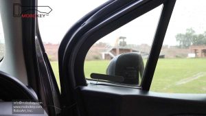
- Remove the tape from the antenna and place the antenna on the side as shown here.
 Testing the connections
Now, testing the device, the car will start before deactivating the engine from the smartphone.
And the car will not start after deactivating the engine from the smartphone.
In the end, pack the wiring and make sure that none of the wires are hanging or not insulated. Use zip ties provided to pack properly.
You can watch the video here.
Mobokey is the smartphone car key.
Download your application here: Go to Play Store or App Store!
Get more info about MoboKey: An App which is your Smartphone Car Key
Connect your car now. Order here!
Control Car via Smartphone!