Once you open the MoboKey One Box, you will find a device, wiring, a relay, some zip ties, double tape, and an installation manual. All of these things will be required while installing the device in your car. MoboKey One allows you to unlock, lock, secure, and share your car using the Bluetooth of your phone.
One Installation Guide:
Push Start Cars
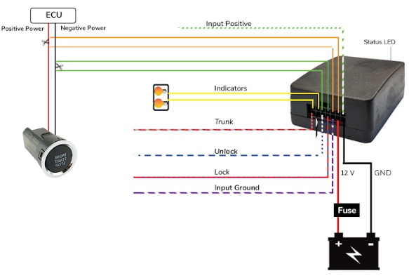
Following instructions are for the cars that start with a push button.
- Connect the Black wire to the Ground and the Red wire to the 12V wire coming directly from the battery.
- Connect Yellow wires to the right and left indicator wires or both wires directly to the hazard switch.
- Connect the Blue/Red (Lock) and Blue/White (Unlock) to the negative triggered lock and unlock wires coming out of the car.
- Take out the push start button and trace the signal wires by pressing the push start button. The wire(s) that sends a pulse by pressing the button is the signal wire(s).
- For the positive pulse wire of the button connect one side of the voltmeter at the negative of the car and the other side at button connector pins one by one.
- For the negative pulse wire of the button connect one side of the voltmeter at the positive of the car and the other side at button connector pins one by one.
- Some cars have both positive pulse wires or both negative pulse wires.
- Once the wires are traced, cut both wires and connect both Green wires in series and both Orange wires in series as shown in the diagram 1.1.
- An RGB status LED is present on the top right side of the device, that shows the current status of the device.
 Key Start Cars
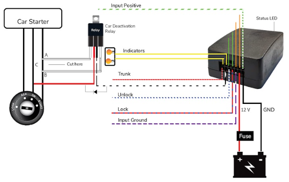
Following instructions are for the cars that start with a key.
- Connect Black wire to Ground and Red wire to 12 V wire coming directly from the battery.
- Connect Yellow wires to right and left indicator wires or one wire directly to hazard switch.
- Connect the Blue/Red (Lock) and Blue/White(Unlock) to the negative triggered lock and unlock wires coming out of the car system.
- For Starter deactivation, cut the starter wire at point C and place the relay in between i.e. One white wire on point B and the other wire on point A as shown in the diagram 1.2. Connect the red wire of the relay with On/Ignition wire at point D.
- Do not remove the diode connected between the Red and Black White wire as it prevents reverse voltage.
- An RGB status LED is present on the top right side of the device that shows the current status of the device.
Download your application here: Go to Play Store or App Store!